All About Manual Lensometer & parts and functions of lensometer, working principle of focimeter (vertometer), optics, calibration, and procedure to read power in the glasses, bifocal glasses, progressive lens, and prism.
What is a manual lensometer?
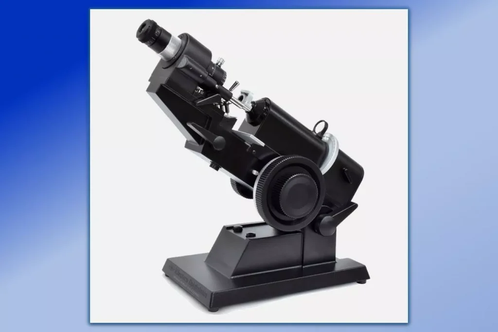
A lensmeter or lensometer or focimeter or vertometer (manual or automated) is a microscope.
The manual lensometer is defined as an ophthalmic instrument that is mainly used by optometrists or opticians to measure the back-vertex (or front-vertex) power of the eyeglasses and contact lenses.
The procedures and techniques of using a lensometer are known as lensometry (lenso=lens, metron=measurement) or focimetry.
To measure the power of the contact lens, special lens support or lens holder is used in a manual lensometer.
Definition: Manual lensometer is a microscope that is used to measure the power of the eyeglasses or contact lenses. This ophthalmic instrument is utilized to accurately measure the back vertex (or front vertex) power of the lens. This device is used by optometrists or opticians in eye clinics and optical shops

Working principle of lensometer
What is the working principle of the lensometer? The manual lensometer is based on the Badal principle.
For precise detection of parallel rays at neutralization, an astronomical telescope is used. The Badal principle is Knapp’s law applied to focimeter.
Manual lensometer and automated (digital)) lensometer are 2 varieties commonly seen in ophthalmic and optometric practices, and optical dispensing.
In focimeter, green (or yellow) light is used as a target to eliminate the effect of chromatic aberrations.
It can measure the power of eyeglasses and contact lenses ranging from +20.00D (diopter) to -20.00D
A manual lensmeter is a telescopic optical device equipped with an optical system and a rotatable target illuminated by a light source.
Automated vs Manual Lensometer
| Manual Lensometer | Automated (digital) Lensometer |
| -gives the accurate power of eyeglasses, contact lenses, and prisms and is mostly seen in optical industries. -it is portable as dry cells or rechargeable batteries are used -require better ideas and special knowledge to use and handle. -more accurate but not as fast as a digital lensmeter. | -fully automatic well-programmed instrument that is mostly seen in clinics. -easy and faster compared to a manual lensometer and can print readings of the lenses. -less accurate when compared to a manual lensmeter. |
Uses of Lensometer
Both manual and digital vertometers are used to determine the following characteristics of lenses and prisms:
-power of single vision, bifocal, trifocal lenses
-power of multifocal (progressive or varifocal) lenses
-optical center location
-major reference point location
-cylinder axis orientation
-prism power/direction
-It is also used during the fabrication process to place marks on the lens to ensure proper placement of the lens.
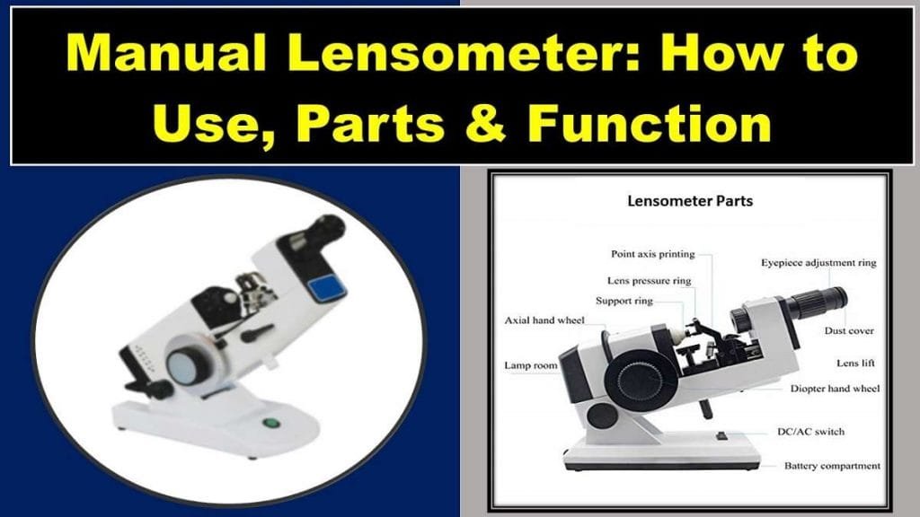
Manual Lensometer Parts and Function
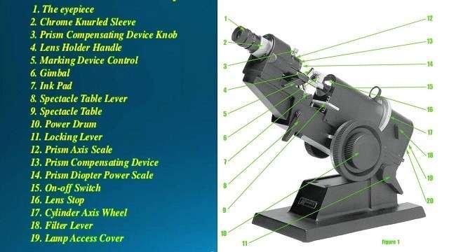
The following manual lensometer parts are commonly seen in all types of focimeters.
- The Eyepiece
- Chrome Knurled Sleeve (Reticle Adjustment Knob)
- Prism Compensating Device Knob
- Lens Holder Handle
- Marking Device Control (Lens Marker)
- Gimbal (Lens Holder)
- Ink Pad
- Spectacle Table Lever
- Spectacle Table
- Power Drum
- Locking Lever
- Prism Axis Scale
- Prism Compensating Device
- Prism Diopter Power Scale
- On-Off Switch
- Cylinder Axis Wheel
- Filter Lever
- Lamp Access Cover
Manual Lensometer Parts and Function:
- The Eyepiece
It is mounted in a screw-type focusing mechanism. It plays an important role in the accuracy of the reading.
So, it is essential to focus the eyepiece on the individual eye (according to the refractive status) of each user. The rubber guard is used to prevent the scratching of the user’s eyewear.
2. Chrome Knurled Sleeve (Lensometer Reticle Adjustment Knob)
It is used to rotate the lensometer Reticle to orient the prism base.
3. Prism Compensating Device Knob
Used to read prism amounts greater than five prism diopters. New models of lensometers have an attached rotary prism to dial in 0 to 25 prism diopters.
4. Lens Holder handle
Holds a lens in place against the aperture.
5. Marking device control (Lens Marker)
Pins controlled by the handle and used to spot (mark) the lens either at Prism Reference Point or Optical Center.
6. Gimbal (Lens Holder)
The lens holder holds the lens in place while taking a reading. Gimbal is a circular piece that swivels with legs and touches the lens and holds it firmly for taking readings.
7. Ink Pad
It holds the spotting ink. Pins of marking device control and ink need to be replaced and re-inked regularly.
8. Spectacle Table Lever
It is used to raise, or lower the level of the spectacle table.
9. Spectacle Table
The resting place for the spectacle frame while neutralizing lens power.
10. Power Drum
The power drum is a hand wheel with numbered scale readings between +20.00 to -20.00 Diopter. The reading interval in scale is usually in 0.12 diopters steps and the steps for higher powers are 0.25 diopters.
11. Locking Lever
It is used to elevate or depress the position of the instrument for an individual’s height or posture.
12. Prism Axis scale
Used for orientation of prism axis.
13. Prism Compensating Device
It is used for verifying a large amount of prism.
14. Prism Diopter Power Scale
It displays a prism amount.
15. On-off Switch
Power switch
16. Lens Stop
It is the aperture against which the lens rests.
17. Cylinder Axis Wheel
It is used to orient and neutralize the cylindrical axis.
18. Filter Lever
Used to engage or remove the green filter.
19. Lamp Access Cover
It provides access to change the manual lensometer bulb.

Optics of manual lensometer
Manual Lensometer: Related Terminology
Mires
thick and thin lines used as measurement images in a lensometer
Sphere
a lens with power being similar in all meridians. It is used to correct simple refractive errors (myopia or hyperopia, also presbyopia). It is measured in diopter.
Cylinder
a lens with different refractive power in different meridians. It is used to correct astigmatism. It is also measured in diopter.
Axis
meridian of cylinder lens with the minimum refractive power. It is perpendicular to the meridian with maximum power. It is expressed in degrees.
Prism
It is a wedge-shaped, transparent material with two flat surfaces inclined at a specific angle and connected at a point called the apex.
The two flat surfaces rest on the base of the prism. It is used to refract or bend light in the required direction.
It is used in ophthalmic lenses mostly to help the eyes to work together (by compensating deviations, field loss, etc.).
How to use a manual lensometer smoothly?
- Fix the manual lensometer on a stable surface, at the comfortable viewing position
- Focus the eyepiece of the manual lensometer each time the instrument is used
- Check the power drum for proper calibration of the manual lensometer
- Place the eyeglass on the movable spectacle table
- Determine the power of spherical lenses
- Determine the power of sphero-cylindrical lenses
Calibration of Lensometer
It means adjusting the device to perform smoothly to get the accurate power of the lenses.
-an eyepiece should be focused manually, each time while determining the power of individual lenses
-fix the lensmeter on a stable surface, at the comfortable viewing position
-set power drum to zero, “0”
-the device should be clean, free of error, and all the knobs should be adjusted correctly
-set the prism compensator to zero
Focusing the eyepiece
It is necessary to focus the eyepiece of a manual lensometer each time the instrument is used, to avoid erroneous readings.
-rotate the eyepiece counter-clockwise until fully extended, as far as possible, from the instrument
-the lensometer reticle (graticule) now appears blurred, while viewing through the eyepiece.
Gently rotate the eyepiece in the clockwise direction until the mires (target crosshairs) and the lensometer reticle just come into focus.
-rotating the eyepiece continuously forces the viewer to accommodate, to keep the reticle in focus.
-with the power drum at zero, the mires and lensometer reticle should be in focus. The inappropriate focus of the eyepiece results in an incorrect reading of lens power.
Check the power calibration
-with no lens or a Plano lens in position, look through the eyepiece of the lensometer. Turn the power wheel (drum) gently into the plus region, and the mires are out of focus.
-slowly rotate the power wheel in the opposite direction (towards the lower plus region) until the target just sharply focuses.
(Note: DO NOT oscillate the drum back and forth for best focus). If the lensometer is in proper calibration, the power wheel will read zero.
-in case the power wheel doesn’t show zero, refocus the eyepiece and recheck the calibration.
If the reading is still not zero, the sustained error should be compensated from the future measurement of lenses with the lensometer.
For example: if the error is +0.50, then 0.50 should be subtracted from future lens power. Similarly, if the error is -0.25, then 0.25 should be added in the future measurement power.
Structures seen through a manual lensometer
The lensometer Reticle (Graticule)
While looking through the eyepiece, the black guide with numbered rings attached to it is visible. This is called a lensometer reticle.
The center of the lensometer reticle consists of a small circle with lines dividing the circle into 4 quarters.
It helps to position the optical center of the lens in the correct area. It also helps to mark and locate the major reference point in the case of prism (grounded or induced) prescription within the lens.
Likewise, it is also important to mark and verify the axis position of sphero-cylindrical lenses. The reticle adjustment knob is used to adjust the position of the manual lensometer reticle.
The Target
It is green (or yellow) in color and appears when the device is switched on. It shows the position of the optical center of the lens. There is a ring of round dots at its center.
The small dots represent the power orientation of the lens as the target rotates with the rotation of the lens.
In the case of a toric lens, the round dots become small lines oriented in one direction.
Positioning the eyeglasses
-Place the spectacle on the movable spectacle table with the temples facing away from you. The lens is held in position by the lens holder.
Center the lens by moving it so that the image of the target made by a lens is aligned at the center of the reticle.
-Pacing the lens at this position allows you to measure the back-vertex power of the lens (normal position of the lens when worn).
If you wish to measure the front-vertex power of the lens, you can change the placement of the spectacle, upside down.
-if testing a pair of glasses, follow the general convention: always check the right lens first, followed by the left lens.
Determining the power of spherical lenses in a manual lensometer
In a spherical lens, all the lines and dots of the target are in perfect focus at a given setting of the power wheel.
- move the lens such that the target is exactly at the center of the reticle.
- rotate the power wheel (from extreme plus area to lower plus and minus area) until the target is clear and sharp. At this position, all the dots and lines should be sharp and separated.
- repeat the same procedure for the left lens.
Determining the power of sphero-cylindrical lenses in a manual lensometer
Neutralizing spherical and cylindrical components of a toric lens involves a completely different approach than you do for neutralizing the power of a spherical lens.
With the help of a few tips, however, you can measure the power very fast and with accuracy. For that, you must pay key attention to the central orientation of the dots and the clarity of lines and dots.
Process of toric lens power measurement in a manual lensometer
Step 1 (finding the spherical power)
- Rotate the power drum until one set of lines and stretched dots become clear. Start from the higher plus area (or lower minus).
- Rotate the axis drum to ensure that the lines are unbroken and clear.
- At this point, note the power reading on the power wheel.
Step 2 (finding the minus cylindrical power)
- Rotate the power drum until the second set of lines and stretched dots become clear. Start from the higher plus area (or lower minus).
- Again, Rotate the axis drum to ensure that the lines are unbroken and clear.
- At this point, note the power reading on the power wheel.
- The second power reading minus the first power reading gives the cylindrical power value of the lens.
Step 3 (finding the axis)
- Observe the direction of the lines and stretched dots at the second reading. Note the axis value towards which the lines are oriented. This is the cylindrical axis of the lens.
- Record your final result. Example –2.00 – 1.50 x 155
- Repeat the same process to measure the back-vertex power of the sphero-cylindrical lens of the left eye.
To transpose the cylinder in plus power, rotate the axis by 90 degrees and start over. Or, you can follow the transposition technique:
- subtract the cylinder power from the sphere power. This will be the spherical power of the given lens.
- change the power sign of the cylindrical power (but the power value will remain the same).
- add 90 degrees to the axis; this will be the new axis of the given lens.
Marking the optical center of the lens
- make sure that the image of mires made by the lens coincides with the center of the target.
- at this particular position, the lens is correctly placed and the optical center can be marked.
- if there is a central ring instead of small dots, the ring can be framed within the lines of the reticle to locate the center.
- mark a dot at the optical center with the spotting ink-marker attached with the ink pad.
- repeat a similar procedure for the left lens.
How to read add power on lensometer?: For bifocal and progressive lenses
Most multifocal lenses are on front surface design. Therefore, to accurately determine the reading power of bifocal, trifocal, or varifocal lenses, front vertex powers should be measured.
For a small amount of power in the reading and distance portion of lenses, it is not necessary to measure the front vertex power, but for higher power (greater than +2.50D), the spectacle should be turned around in the lensometer to measure the front vertex power.
(NOTE: higher reading power will show more plus than they actually are when using the back-vertex measurement instead of the front-vertex measurement.)
- after measuring the spherical and cylindrical power of the distance portion of a multifocal lens, place the reading portion of a lens on the lens stop and refocus on the single line.
- the add, or reading power, is the difference between the distance power and the reading portion of spherical power.
- to determine the difference in power, focus only on the power of the single line (ignore the power of the second set of lines) in the reading part of the lens.
Example:
Distance Rx: +2.50/-0.50 x 60
Reading area power: +5.50
Final Rx: +2.50/-0.50 x 60/+3.00D
When measuring add power in progressive addition lenses (PAL), select the area of least distortion in both the distance and the reading portions of the lenses.
Similarly, measure the reading power at the area as close to the bottom of the lens as possible.
How to read prism on lensometer?
If you are confused about how to read prism on lensometer, follow the simple tricks. If there are less than 5 prism diopters in the lens, follow the given steps:
- count the number of black concentric circles from the center of the target to the center of the vertical and horizontal cross of mires. Each circle represents 1 prism diopter.
- to record the base of the prism, determine the direction of displacement of the mires as:
- mires displaced upward-prism is base up
- mires displaced downward-prism is base down
- mires displaced towards the nose-prism is base in
- mires displaced towards temple-prism is base out
How to read prism on lensometer if prism power is greater than 5 prism
To measure the prism power greater than 5 prism diopters, use the auxiliary prisms in a manual lensometer.
Because the single (or both) sphere line is not visible in the display, in prism power greater than 5 prism diopters.
- hold the loose prism (s) over the lens. The power of loose prism which brings the mires back to the center of the graticule is the power of the prism in the lens but in the opposite orientation.
Also Read:
⇒ 5 Tips on Eye Health: How to Keep Eyes Healthy and Beautiful
⇒ Understand All About Lazy Eye (Amblyopia) Before It’s Too Late
⇒ Now Is The Time For You To Know About the Impact Of Using Gadgets On Eyes.


